This information is taken from Workshop Manuals TSD2476 (Series I models) & TSD4200 (Series II models), Section G. We advise only undertaking work on the hydraulic system if you have read and can refer to the relevant manual.
Introduction
It is essential that, in order to obtain optimum performance, the hydraulic systems must at all times be completely free from air. The two hydraulic systems are recirculatory and therefore, if air is allowed to enter them at any point, it could cause reduced efficiency.
The front hydraulic reservoir supplies fluid to the number one system - the front brake pump, the front hydraulic accumulator (on engine A bank on Series II models), the lower distribution valve (Series I models)/upper brake distribution valve (Series II models), the G valve, the front calipers of the front brakes and the upper cylinders of the rear brake calipers.
The rear hydraulic reservoir supplies fluid to the number two system - the rear brake pump, the rear hydraulic accumulator, the automatic height control system, the upper brake distribution valve (Series I models)/ lower distribution valve (Series II models), the rear calipers of the front brakes and the lower cylinders of the rear brake calipers.
Bleed screws are fitted to the systems at various points and it is imperative, should a system be disturbed in service and pipes disconnected, that the entire system downstream of this point be thoroughly bled to expel all air.
The bleed screws are fitted to the following components: the hydraulic accumulators, the left hand pressure switch (Series II models),the brake calipers and the height control rams.
Whilst bleeding is being carried out it is essential that the two reservoir compartments are kept topped up, above the topping up level on the sight glass, with clean RR363 fluid.
Note: Bleed screws must be torque tightened to between 8 lbft and 10 lbft (1.10 kgm and 1.38 kgm).
If any work on the system requires removal of any pipes or components, then disconnect the battery.
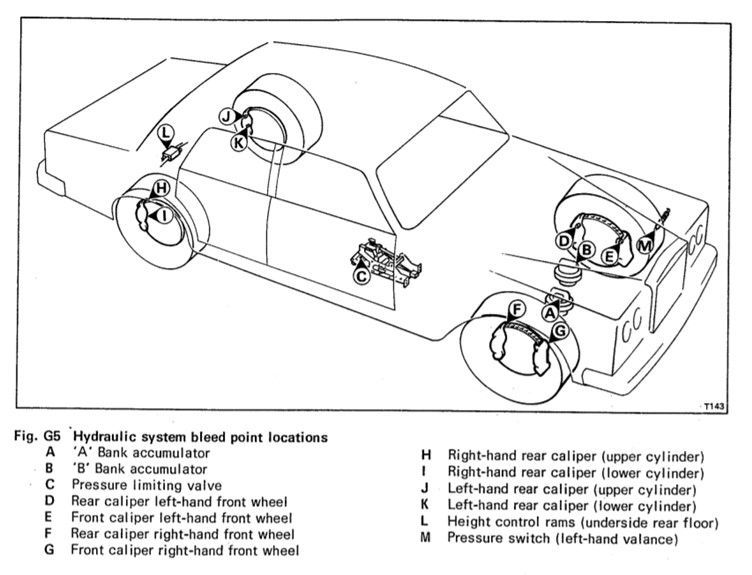
Bleed the system in the following sequence (see Fig G5 for location references)
Depressurising both systems
Open bleed screws at points A, B and C (see Fig. G5)
Depress brake pedal, start the engine and run at between 750-800rpm.
Check facia warning lights to ensure Brake 1 and Brake 2 low pressure warning lights are illuminated.
Keep brake pedal depressed and the engine running.
Bleeding the systems
Allow bleed points A, B and C to bleed until free of air bubbles.
Step 1. Open bleed screws D and E and allow bleeding to start.
Step 2. Close bleed screws A, B and C.
Step 3. Open bleed screws F and G and allow bleeding to start.
Step 4. Close bleed screws D and E once free of air bubbles.
Step 5. Open bleed screws H and I and allow bleeding to start.
Step 6. Close bleed screws D and E once free of air bubbles.
Step 7. Open bleed screws J and K and allow bleeding to start.
Step 8. Close bleed screws H and I once free of air bubbles.
Step 9. Close bleed screws J and K once free of air bubble.
Step 10. Release brake pedal but keep engine running.
Rear height control system bleeding
Car needs to be on its wheels
Step 11. Add weight to rear of car to activate levelling valves.
Allow systems to pressurise, check facia warning lights to ensure brake system 1 and 2 low pressure warning lights are extinguished.
Step 12. Open bleed screw L and allow to bleed until free of air bubbles.
Step 13. Switch off the engine.
Step 14. Open bleed screw M and allow to bleed until free of air bubbles.
Step 15. Close bleed screw M.
Take care when bleeding at above points L and M as system will be at full pressure!
Step 16. Check fluid reservoir levels and top-up if necessary. Make sure all bleed nipple dust covers are refitted. Road test the car.
Please note that the rear height control ram bleed screws on later Series II models are on the inside of the sills.
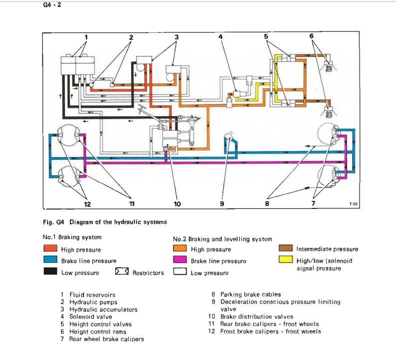
The diagram above is taken from the Series II Workshop Manual TSD4200 and shows the flow of fluid around the hydraulic systems.