Suitable for Rolls-Royce & Bentley models between:
- 1965-1980 (From VIN 11800 onwards)
- 1980-2003 (From VIN 1001 up to 27798)
This information is taken from Workshop Manual TSD2476, Section H.
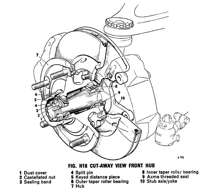
1. Fit the distance piece, with the chamfered edge leading, onto the stub axle to abut the shoulder adjacent to the yoke.
2. Position the hub onto the stub axle, fit the key washer, then finger tighten the castellated nut sufficiently to remove any hub end-float.
3. Using a dial test indicator mounted adjacent to the brake disc, measure the run-out of the disc at the maximum radius possible; this must not exceed 0.007 in. (0,178 mm.) total indicator reading.
Note: The reading obtained is a measure of the tolerances of all the components and if the run-out figure exceeds this measurement, dismantle the hub and brake disc to investigate the cause of the run-out.
4. If the run-out figure is within limits, remove the hub from the stub axle and pack the hub with approximately 13 oz. (42,64 gm.) of the approved grease. The grease should be liberally smeared on the bearings and on the inner wall of the hub so that it is not disturbed when the hub is fitted to the stub axle.
5. Fit the hub, key washer and castellated nut.
6. Using a 0.004 in. (0,102 mm.) feeler gauge inserted between the outer bearing and key washer, or a suitable dial test indicator equipment. tighten the castellated nut sufficiently to grip the feeler gauge lightly or to give a reading of 0.002 in. to 0.006 in. (0,051 mm. to 0,152 mm.) end-float on the dial test indicator. Continuous rotation of the hub is essential during this operation to ensure that the taper rollers seat correctly.
7. When the correct end-float is obtained, unscrew the castellated nut to align the nearest slot in the nut with the nearest hole in the stub axle.
8. Measure the end-float by either of the two methods, and select a suitable key washer to give the correct end-float.
Note: Key washers are provided in thicknesses of 0.138 in. and 0.140 in. (3,51 mm. and 3,56 mm.). Incorrect setting of the bearings, either too slack or too tight will result in premature bearing wear.
9. Fit a new split pin and sealing band. Bend back the split pin legs and crimp the ends of the sealing band to lock the nut in position. 10. Smear approximately 3 oz. (14,21 gm.) of the approved grease into the base of the dust cover. Fit the dust cover by tapping into position on the hub with a nylon hammer. Whilst fitting this cover, ensure that the earthing strip is in the correct position to make contact with the stub axle end face.
11. To fit the brake calipers, reverse the procedure
12. Fit the road wheel; screw on the wheel nuts to be refitted. but do not tighten.
13. Lower the car from the jack and supports and fully tighten the road wheel nuts to the torque figure given in Chapter P - Torque Tightening Figures.
14. Fit the wheel disc/hub cover plate.